우선 Barrel Distortion이란 무엇인지 다음의 사진을 보면 명확해진다.
[참고자료]
http://www.tannerhelland.com/4743/simple-algorithm-correcting-lens-distortion/
http://sprg.massey.ac.nz/ivcnz/Proceedings/IVCNZ_73.pdf
2015년 7월 9일 목요일

2015년 7월 1일 수요일
[작업중] TP-LINK WR703N 설정하기
1. OpenWRT의 배포본 설치하기
다음의 바이너리이미지를 다운로드한다.
구체적인 설치 방법은 다음의 링크를 통해서 해결하자.
2.WIFI 설정하기
WR703N은 기본적으로 WIFI가 비활성화 되어 있다. 우선 보드에 접속한다. 보드에 접속하는 방법은 이더넷을 연결하거나 보드에서 RS232포트를 집적 뽑아내어 터미널로
보드에 접속하여 /etc/config/network 파일에 다음과 같이 수정한다.
그리고 구체적인 무선통신 설정은 /etc/config/wireless 파일을 다음과 같이 수정하여 해결한다.
리부팅한다. 참고적으로 위의 와이파이 네트워크는 주변의 사용 가능한 SSID와 암호이어야 한다. 그래야 인터넷에 접속하여 다음의 사항들을 진행할 수 있다.
3. sysupgrade 설치
4. opkg 설치
용량한계에 따른 문제들
tftp 설치
커스텀 롬 설치하기
10. mjpg-streamer 설치하기
http://wiki.openwrt.org/doc/howto/webcam
다음의 바이너리이미지를 다운로드한다.
https://downloads.openwrt.org/snapshots/trunk/ar71xx/generic/openwrt-ar71xx-generic-tl-wr703n-v1-squashfs-factory.bin
구체적인 설치 방법은 다음의 링크를 통해서 해결하자.
http://wiki.xinchejian.com/wiki/Install_OpenWRT_on_TPlink_WR703N
https://translate.google.com/translate?sl=auto&tl=en&js=y&prev=_t&hl=ko&ie=UTF-8&u=http%3A%2F%2Fwww.geeknimo.com%2F2013%2F10%2F14%2Fopenwrt%25E7%259A%2584%25E7%25A0%2594%25E4%25B9%25A0%25E7%25AC%2594%25E8%25AE%25B0%25E4%25BA%258C%2F&edit-text=
2.WIFI 설정하기
WR703N은 기본적으로 WIFI가 비활성화 되어 있다. 우선 보드에 접속한다. 보드에 접속하는 방법은 이더넷을 연결하거나 보드에서 RS232포트를 집적 뽑아내어 터미널로
http://www.instructables.com/id/TL-WR703N-serial-port/
보드에 접속하여 /etc/config/network 파일에 다음과 같이 수정한다.
config interface 'wan'
             option ifname 'wlan0'
             option proto 'dhcp'
그리고 구체적인 무선통신 설정은 /etc/config/wireless 파일을 다음과 같이 수정하여 해결한다.
             # REMOVE THIS LINE TO ENABLE WIFI:
config wifi-iface
             option device radio0
             option network wan
             option mode sta
             option ssid '와이파이네트워크이름'
             option encryption psk
             option key '와이파이네트워크암호'
리부팅한다. 참고적으로 위의 와이파이 네트워크는 주변의 사용 가능한 SSID와 암호이어야 한다. 그래야 인터넷에 접속하여 다음의 사항들을 진행할 수 있다.
3. sysupgrade 설치
4. opkg 설치
용량한계에 따른 문제들
tftp 설치
커스텀 롬 설치하기
10. mjpg-streamer 설치하기
http://wiki.openwrt.org/doc/howto/webcam
mjpg-streamer 컴파일
소스 코드를 고쳐서 mjpg-streamer를 사용해야 하기 때문에 소스코드를 직접 컴파일해 보았다.
우선 가장 먼저 맞이하게 되는 문제는 다음과 같다.
mjpg_streamer.c:27:28: fatal error: linux/videodev.h: No such file or directory
이건 다음의 심볼릭 링크를 만들어서 해결하면된다.
그리고 두 번째 봉착하게 되는 문제는 unsigned long int와 int * 사이에 발생하는 cast 오류이다. 이것은 문제가 되는 파일의 컴파일을 무시하는 방식으로 처리하자. mjpg-streamer의 Makefile의 다음 라인을
아래와 같이 수정한다.
여전히 문제점이 하나 남아 있다. plugins/input_uvc/uvcvideo.h파일에 다음 라인을 추가한다.
아직 혼돈 스럽지만 컴파일은 이로써 가능하다.
우선 가장 먼저 맞이하게 되는 문제는 다음과 같다.
mjpg_streamer.c:27:28: fatal error: linux/videodev.h: No such file or directory
이건 다음의 심볼릭 링크를 만들어서 해결하면된다.
# ln -s /usr/include/libv4l1-videodev.h /usr/include/linux/videodev.h
그리고 두 번째 봉착하게 되는 문제는 unsigned long int와 int * 사이에 발생하는 cast 오류이다. 이것은 문제가 되는 파일의 컴파일을 무시하는 방식으로 처리하자. mjpg-streamer의 Makefile의 다음 라인을
plugins: input_uvc.so output_file.so output_http.so input_testpicture.so output_autofocus.so inputgspcav1.so
아래와 같이 수정한다.
plugins: input_uvc.so output_file.so output_http.so input_testpicture.so output_autofocus.so
여전히 문제점이 하나 남아 있다. plugins/input_uvc/uvcvideo.h파일에 다음 라인을 추가한다.
#include"linux/videodev2.h"
아직 혼돈 스럽지만 컴파일은 이로써 가능하다.
2015년 4월 23일 목요일
주목할 만한 프로젝트들
1.해커데이에서 지구의 날 특집으로 소개된 초소형 스펙트로 미터가 흥미롭다.
https://hackaday.io/project/4141-c12666ma-micro-spectrometer
핵심은 하마마츠에서 판매하는 캔 타입의 C12666MA는 chip 타입의 grating과 linear CMOS 센서로 구성되며 이러한 개념으로 계속 버전업을 해왔나 보다. 응답유효 파장대가 340nm 에서 780nm으로 일반적인 형광 반응과 컬러 측정이 가능할 것이다. 아래의 데이터 시트를 살펴보면 다른 파장대의 센서도 판매하고 있다. 가격이 아직 착한 상황은 아니지만 약 200~300 달러 인 것 같다. 계속 주의 깊게 살펴보아야 겠다.
http://www.hamamatsu.com/resources/pdf/ssd/c12666ma_kacc1216e.pdf
2. 마찬가지로 해커데이에서 소개된 wifi 모듈이다. 단순한 wifi모듈은 아니고 Atheros사의 지금은 Qualcomm사에 합병된 회사의 AR9331로 구성된 하나의 리눅스 시스템이다.
http://hackaday.com/2015/04/22/kickstarting-even-more-router-based-dev-boards/
그 구성이 한동안 유행되었던 OpenWRT기기인 DT-Link사의 WR703n이 떠오르게한다.
http://daviddarts.com/piratebox-diy-openwrt/
조금만 살펴보면 위의 기기를 사용한 다양한 프로젝트를 고려하면 그 유용성은 상당할 것 같다.
아무튼 조만간 사용해야 할 일들이 많을 것 같다.
3. LED 모듈인데 내가 필요한 용도와는 다르지만 그 구성이 참고해 볼만 한다. 참고삼아 하나 구매해 보고 싶지만. 아무튼 살펴보자.
https://www.adafruit.com/products/1430
https://hackaday.io/project/4141-c12666ma-micro-spectrometer
핵심은 하마마츠에서 판매하는 캔 타입의 C12666MA는 chip 타입의 grating과 linear CMOS 센서로 구성되며 이러한 개념으로 계속 버전업을 해왔나 보다. 응답유효 파장대가 340nm 에서 780nm으로 일반적인 형광 반응과 컬러 측정이 가능할 것이다. 아래의 데이터 시트를 살펴보면 다른 파장대의 센서도 판매하고 있다. 가격이 아직 착한 상황은 아니지만 약 200~300 달러 인 것 같다. 계속 주의 깊게 살펴보아야 겠다.
http://www.hamamatsu.com/resources/pdf/ssd/c12666ma_kacc1216e.pdf
2. 마찬가지로 해커데이에서 소개된 wifi 모듈이다. 단순한 wifi모듈은 아니고 Atheros사의 지금은 Qualcomm사에 합병된 회사의 AR9331로 구성된 하나의 리눅스 시스템이다.
http://hackaday.com/2015/04/22/kickstarting-even-more-router-based-dev-boards/
그 구성이 한동안 유행되었던 OpenWRT기기인 DT-Link사의 WR703n이 떠오르게한다.
http://daviddarts.com/piratebox-diy-openwrt/
조금만 살펴보면 위의 기기를 사용한 다양한 프로젝트를 고려하면 그 유용성은 상당할 것 같다.
아무튼 조만간 사용해야 할 일들이 많을 것 같다.
3. LED 모듈인데 내가 필요한 용도와는 다르지만 그 구성이 참고해 볼만 한다. 참고삼아 하나 구매해 보고 싶지만. 아무튼 살펴보자.
https://www.adafruit.com/products/1430
2015년 3월 31일 화요일
Debian 기반 리눅스 시스템에서 Adafuit의 Trinket 사용하기
1. 사전 작업 (arduino 설치)
# apt-get arduino
2. 디바이스 필터 설정
아래의 설정 파일을 생성하고 내용을 추가한다.
/etc/udev/rules.d/95-usbtiny.rules
#Adafruit Trinket
ACTION=="add", SUBSYSTEM=="usb", ATTR{idVendor}=="1781", ATTR{idProduct}=="0c9f", GROUP="dialout", MODE="0666"
3. avrdude 설정 파일 변경
/etc/avrdude.conf 에서 다음의 항목들을 변경한다.
# chiperasetime = 0;
chiperasetime = 900000;
...
4. arduino IDE를 추가 파일 설치하기
다음의 주소로 가서
https://learn.adafruit.com/introducing-trinket/setting-up-with-arduino-ide
Step 1. Add ATtiny85 Support 밑에 있는 다운로드 항목을 내려 받는다.
내려 받은 trinkethardwaresupport.zip을 압축해제한다.
해제된 파일들중 variants 디렉토리밑의 디렉토리들을 (tiny8, tiny14) 통체로
/usr/share/arduino/hardware/arduino/variants밑으로 이동한다.
그리고 /usr/share/arduino/hardware/arduino/boards.txt 파일에 다음 항목들을 추가한다.
그리고 arduino IDE에서 개발 보드의 제어 권을 획득하기 위해서 다음 명령을 수행한다.
# adduser <사용자명> dialout
5. Trinket을 연결하고 인식 여부를 확인해 보자.
주의 사항: 해당 보드는 하드웨어적으로 USB 포트를 지원하지 않기 때문에 전원 인가 후 10초 동안만 펌웨어 다운로드와 보드 인식이 가능하다. 달리 말하자면 보드를 제대로 인식하고 작성된 프로그램을 업로드 하기 위해서 리셋을 사전에 누르고 10초 안에 해당 작업을 해야 한다.
# avrdude -c usbtiny -p attiny8
6. 간단한 프로그래을 테스트 해보자.
마찬가지로 업로드 하기 전에 리셋 버튼을 누르고 업로드는 10초 안에 이루어져야한다.
/*
Blink
Turns on an LED on for one second, t/*
Blink
Turns on an LED on for one second, then off for one second, repeatedly.
This example code is in the public domain.
To upload to your Gemma or Trinket:
1) Select the proper board from the Tools->Board Menu
2) Select USBtinyISP from the Tools->Programmer
3) Plug in the Gemma/Trinket, make sure you see the green LED lit
4) For windows, install the USBtiny drivers
5) Press the button on the Gemma/Trinket - verify you see
the red LED pulse. This means it is ready to receive data
6) Click the upload button above within 10 seconds
*/
int led = 1; // blink 'digital' pin 1 - AKA the built in red LED
// the setup routine runs once when you press reset:
void setup() {
// initialize the digital pin as an output.
pinMode(led, OUTPUT);
}
// the loop routine runs over and over again forever:
void loop() {
digitalWrite(led, HIGH);
delay(500);
digitalWrite(led, LOW);
delay(500);
}
hen off for one second, repeatedly.
This example code is in the public domain.
To upload to your Gemma or Trinket:
1) Select the proper board from the Tools->Board Menu
2) Select USBtinyISP from the Tools->Programmer
3) Plug in the Gemma/Trinket, make sure you see the green LED lit
4) For windows, install the USBtiny drivers
5) Press the button on the Gemma/Trinket - verify you see
the red LED pulse. This means it is ready to receive data
6) Click the upload button above within 10 seconds
*/
int led = 1; // blink 'digital' pin 1 - AKA the built in red LED
// the setup routine runs once when you press reset:
void setup() {
// initialize the digital pin as an output.
pinMode(led, OUTPUT);
}
// the loop routine runs over and over again forever:
void loop() {
digitalWrite(led, HIGH);
delay(500);
digitalWrite(led, LOW);
delay(500);
}
# apt-get arduino
2. 디바이스 필터 설정
아래의 설정 파일을 생성하고 내용을 추가한다.
/etc/udev/rules.d/95-usbtiny.rules
#Adafruit Trinket
ACTION=="add", SUBSYSTEM=="usb", ATTR{idVendor}=="1781", ATTR{idProduct}=="0c9f", GROUP="dialout", MODE="0666"
3. avrdude 설정 파일 변경
/etc/avrdude.conf 에서 다음의 항목들을 변경한다.
#------------------------------------------------------------
# ATtiny85
#------------------------------------------------------------

part
     id            = "t85";
     desc          = "ATtiny85";
...
# chiperasetime = 0;
chiperasetime = 900000;
...
# delay  = 6;
 delay  = 12;
...
#         min_write_delay = 4500;
#         max_write_delay = 4500;
         min_write_delay = 30000;
         max_write_delay = 30000;
4. arduino IDE를 추가 파일 설치하기
다음의 주소로 가서
https://learn.adafruit.com/introducing-trinket/setting-up-with-arduino-ide
Step 1. Add ATtiny85 Support 밑에 있는 다운로드 항목을 내려 받는다.
내려 받은 trinkethardwaresupport.zip을 압축해제한다.
해제된 파일들중 variants 디렉토리밑의 디렉토리들을 (tiny8, tiny14) 통체로
/usr/share/arduino/hardware/arduino/variants밑으로 이동한다.
그리고 /usr/share/arduino/hardware/arduino/boards.txt 파일에 다음 항목들을 추가한다.
gemma.name=Adafruit Gemma 8MHz
gemma.bootloader.low_fuses=0xF1
gemma.bootloader.high_fuses=0xD5
gemma.bootloader.extended_fuses=0xFE
gemma.upload.maximum_size=5310
gemma.build.mcu=attiny85
gemma.build.f_cpu=8000000L
gemma.build.core=arduino:arduino
gemma.build.variant=tiny8

trinket3.name=Adafruit Trinket 8MHz
trinket3.bootloader.low_fuses=0xF1
trinket3.bootloader.high_fuses=0xD5
trinket3.bootloader.extended_fuses=0xFE
trinket3.upload.maximum_size=5310
trinket3.build.mcu=attiny85
trinket3.build.f_cpu=8000000L
trinket3.build.core=arduino:arduino
trinket3.build.variant=tiny8

trinket5.name=Adafruit Trinket 16MHz
trinket5.bootloader.low_fuses=0xF1
trinket5.bootloader.high_fuses=0xD5
trinket5.bootloader.extended_fuses=0xFE
trinket5.upload.maximum_size=5310
trinket5.build.mcu=attiny85
trinket5.build.f_cpu=16000000L
trinket5.build.core=arduino:arduino
trinket5.build.variant=tiny8

##############################################################
그리고 arduino IDE에서 개발 보드의 제어 권을 획득하기 위해서 다음 명령을 수행한다.
# adduser <사용자명> dialout
5. Trinket을 연결하고 인식 여부를 확인해 보자.
주의 사항: 해당 보드는 하드웨어적으로 USB 포트를 지원하지 않기 때문에 전원 인가 후 10초 동안만 펌웨어 다운로드와 보드 인식이 가능하다. 달리 말하자면 보드를 제대로 인식하고 작성된 프로그램을 업로드 하기 위해서 리셋을 사전에 누르고 10초 안에 해당 작업을 해야 한다.
# avrdude -c usbtiny -p attiny8
6. 간단한 프로그래을 테스트 해보자.
마찬가지로 업로드 하기 전에 리셋 버튼을 누르고 업로드는 10초 안에 이루어져야한다.
/*
Blink
Turns on an LED on for one second, t/*
Blink
Turns on an LED on for one second, then off for one second, repeatedly.
This example code is in the public domain.
To upload to your Gemma or Trinket:
1) Select the proper board from the Tools->Board Menu
2) Select USBtinyISP from the Tools->Programmer
3) Plug in the Gemma/Trinket, make sure you see the green LED lit
4) For windows, install the USBtiny drivers
5) Press the button on the Gemma/Trinket - verify you see
the red LED pulse. This means it is ready to receive data
6) Click the upload button above within 10 seconds
*/
int led = 1; // blink 'digital' pin 1 - AKA the built in red LED
// the setup routine runs once when you press reset:
void setup() {
// initialize the digital pin as an output.
pinMode(led, OUTPUT);
}
// the loop routine runs over and over again forever:
void loop() {
digitalWrite(led, HIGH);
delay(500);
digitalWrite(led, LOW);
delay(500);
}
hen off for one second, repeatedly.
This example code is in the public domain.
To upload to your Gemma or Trinket:
1) Select the proper board from the Tools->Board Menu
2) Select USBtinyISP from the Tools->Programmer
3) Plug in the Gemma/Trinket, make sure you see the green LED lit
4) For windows, install the USBtiny drivers
5) Press the button on the Gemma/Trinket - verify you see
the red LED pulse. This means it is ready to receive data
6) Click the upload button above within 10 seconds
*/
int led = 1; // blink 'digital' pin 1 - AKA the built in red LED
// the setup routine runs once when you press reset:
void setup() {
// initialize the digital pin as an output.
pinMode(led, OUTPUT);
}
// the loop routine runs over and over again forever:
void loop() {
digitalWrite(led, HIGH);
delay(500);
digitalWrite(led, LOW);
delay(500);
}
2015년 3월 25일 수요일
캐패시터의 X5R과 X7R의 차이점 ?
간단하다 각각의 문자가 의미하는 내용을 알면 명확해진다.
X : 동작상태의 최저 온도가 -55℃
5 : 동작상태의 최고 온도가 +85℃
R : 캐패시턴스의 오차 범위가 ± 15%
요약하자면 X5R이 의미하는 것은 동작온도 범위가 -55℃에서 +85℃이고,캐패시턴스의 오차범위는 ± 15%가 된다.
X : 동작상태의 최저 온도가 -55℃
7 : 동작상태의 최고 온도가 +125℃
R : 캐패시턴스의 오차 범위가 ± 15%
요약하자면 X5R이 의미하는 것은 동작온도 범위가 -55℃에서 +125℃이고,캐패시턴스의 오차범위는 ± 15%가 된다.
결국 X5R과 X7R의 차이는 동작 할 수 있는 최고 온도의 차이 밖에 없다.
X : 동작상태의 최저 온도가 -55℃
5 : 동작상태의 최고 온도가 +85℃
R : 캐패시턴스의 오차 범위가 ± 15%
요약하자면 X5R이 의미하는 것은 동작온도 범위가 -55℃에서 +85℃이고,캐패시턴스의 오차범위는 ± 15%가 된다.
X : 동작상태의 최저 온도가 -55℃
7 : 동작상태의 최고 온도가 +125℃
R : 캐패시턴스의 오차 범위가 ± 15%
요약하자면 X5R이 의미하는 것은 동작온도 범위가 -55℃에서 +125℃이고,캐패시턴스의 오차범위는 ± 15%가 된다.
결국 X5R과 X7R의 차이는 동작 할 수 있는 최고 온도의 차이 밖에 없다.
2015년 2월 17일 화요일
씽크패드 x220의 Full HD LCD로 변경 하기 위한 자료들
[추가 : 가장 최근의 성공 사례 http://tech.vectro.ca/prototype-x220-fhd-mod/ ]
어느 독일인이 중국어 한국어 영어를 넘나들며 일목요연하게 자료를 모아 두었다.
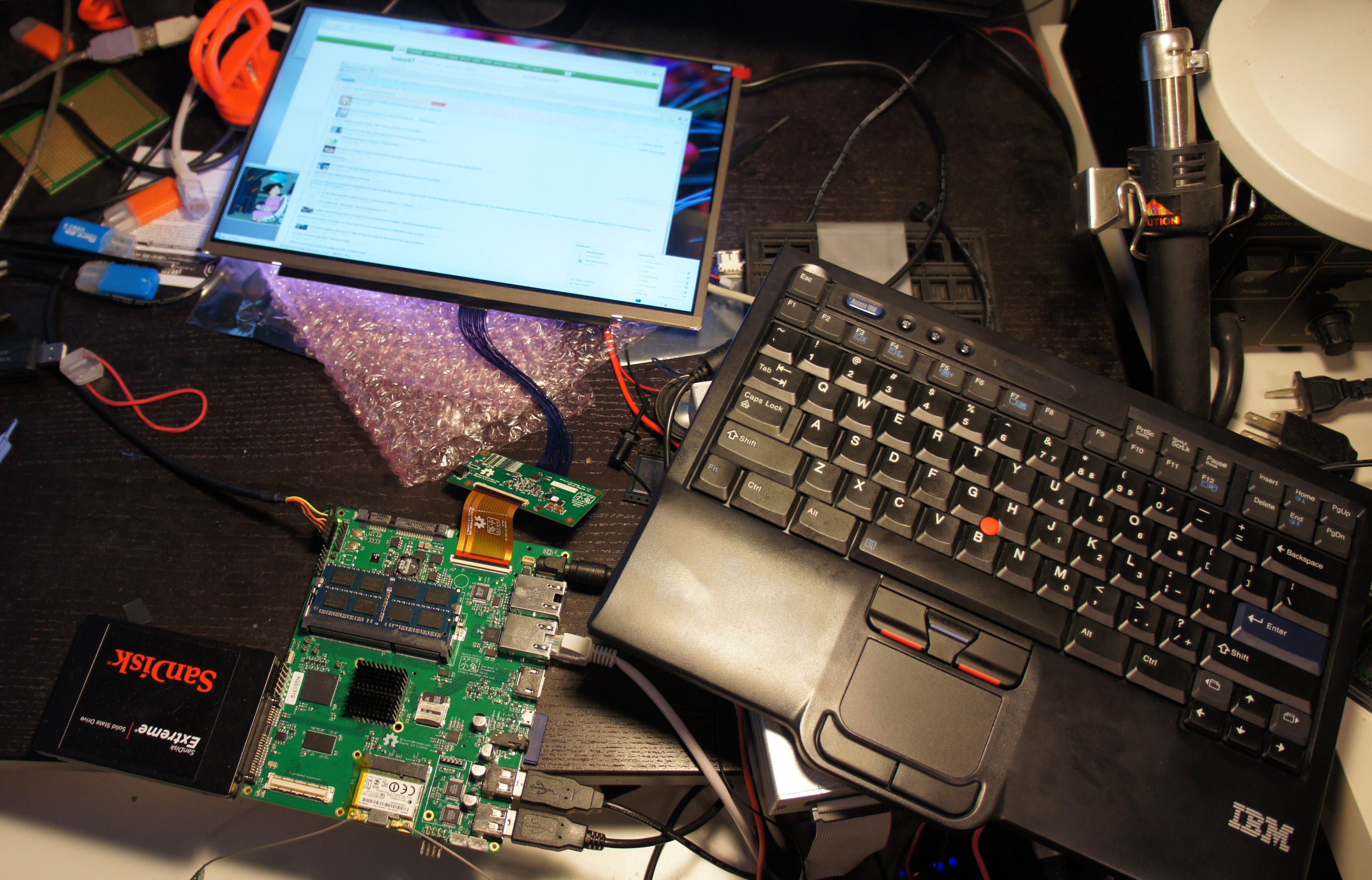
현재 x240s 모델의 경우 FHD LCD 패널을 지원하지만 x230까지의 모델은 지원하지 못하고 있다. x220과 x230 모델에서 FHD LCD 패널을 사용하지 못하는 가장 큰 이유는 LCD 인터페이스가 LVDS 방식이어서 FHD LCD 패널이 지원하는 eDP와 맞지 않는 것이다. 해당 글에서도 알 수 있듯이 LeoKim이라는 한국분이 이미 FHD LCD 장착을 성공 하였다. 핵심은 LVDS->를 eDP로 변환하는 변환기판을 제작하고 그에 따른 케이블 제작과 바이오스 변경이 필요한 듯 싶다. 아무튼 쉽지 않은 작업인 것 같다. 시간을 두고 알아 봐야 겠다.
DP/eDP에 관한 정보들
http://www.intel.com/content/dam/www...logy-paper.pdf
http://dp2retina.rozsnyo.com/
http://abusemark.com/store/index.php...products_id=47
http://www.tarduino.cc/2013_04_01_archive.html
http://emerythacks.blogspot.de/2013/...lcd-to-pc.html
http://www.cables-oem.com/e_products/?big_id=20
LVDS-eDP 변환기
http://www.hy-line.de/de/firmengrupp...parade/ps8622/
http://www.paradetech.com/products/d...at-converters/
http://www.paradetech.com/products/d...25-dp-to-lvds/
http://www.paradetech.com/products/d...erters/ps8623/
http://www.chrontel.com/index.php/pr...ds/edp--per-dp
http://www.chrontel.com/index.php/pr...ews/read/id/1/
http://www.st.com/web/catalog/mmc/FM128/SC1386/SS1485
http://www.st.com/web/catalog/mmc/FM...N1695/PF250895
http://www.chrontel.com/media/Datash...1bs%201.11.pdf
http://bunniefoo.com/novena/pvt1_release/eDP_adapter_dvt1.PDF
http://bunniefoo.com/novena/novena-laptop-dev.jpg
바이오스 변경
https://www.bios-mods.com/forum/index.php
한국 사이트의 성공 사례
X220 LVDS FHD LCD compare LCD VS EDP
World First X220/X230 FHD
Kabel und Interface
X220 Tablet FHD (Proof)
Connector in order for the reconstruction
중국 사이트의 사례들
X220 FHD Mod thread (kaum Infos, die Bilder sind die gleichen wie auf thinkpads.kr)
X220T FHD Mod thread (nur Proof-Bilder und warum der Mod beim X230T nicht klappt) + QHD ist im T420/T420s/T430/T430s möglich
T410S 13.3" ( 16:10 , FHD, 1920x1080, IPS) Modification
T420S/T430s 14.0 "IPS FHD Modifcation success (hier gibts mehr Infos zu erforderlichen Schritten des Bios-Mods, Schaltpläne, Bauteile die man verlöten muss), Anhänge gibts hier
Diskussion zu eDP am X301 Anhänge gibts hier
QHD (2560x1440) im T430s Bilder gibts hier
X1 Carbon mit FHD indem die Southbridge kurzzeitig abgelötet wird und Drähte angebracht werden. Bilder gibts hier. Auf diese Weise soll FHD am X230T doch möglich sein, Bilder hier.
Der Mod am X201 (11,6" FHD) ging auch schon über geklaute edP/DP Signale und Modbios, in den Threads gibt es aber keine weiteren relevanten Infos
12,5" FHD Displays
LP125WF1-SPA1/SPE2 (Dell XPS 12)
LP125WF1-SPA2/SPA3/SPA4/SPB1/SPD1
LP125WF2-SPB1 (X240, Thinkpad Yoga) - touch
LP125WF2-SPB2 (X240) - non-touch
[출처]
http://thinkpad-forum.de/threads/146962-Full-HD-im-X220-X230-mit-diesem-Panel/page10
어느 독일인이 중국어 한국어 영어를 넘나들며 일목요연하게 자료를 모아 두었다.
현재 x240s 모델의 경우 FHD LCD 패널을 지원하지만 x230까지의 모델은 지원하지 못하고 있다. x220과 x230 모델에서 FHD LCD 패널을 사용하지 못하는 가장 큰 이유는 LCD 인터페이스가 LVDS 방식이어서 FHD LCD 패널이 지원하는 eDP와 맞지 않는 것이다. 해당 글에서도 알 수 있듯이 LeoKim이라는 한국분이 이미 FHD LCD 장착을 성공 하였다. 핵심은 LVDS->를 eDP로 변환하는 변환기판을 제작하고 그에 따른 케이블 제작과 바이오스 변경이 필요한 듯 싶다. 아무튼 쉽지 않은 작업인 것 같다. 시간을 두고 알아 봐야 겠다.
DP/eDP에 관한 정보들
http://www.intel.com/content/dam/www...logy-paper.pdf
http://dp2retina.rozsnyo.com/
http://abusemark.com/store/index.php...products_id=47
http://www.tarduino.cc/2013_04_01_archive.html
http://emerythacks.blogspot.de/2013/...lcd-to-pc.html
http://www.cables-oem.com/e_products/?big_id=20
LVDS-eDP 변환기
http://www.hy-line.de/de/firmengrupp...parade/ps8622/
http://www.paradetech.com/products/d...at-converters/
http://www.paradetech.com/products/d...25-dp-to-lvds/
http://www.paradetech.com/products/d...erters/ps8623/
http://www.chrontel.com/index.php/pr...ds/edp--per-dp
http://www.chrontel.com/index.php/pr...ews/read/id/1/
http://www.st.com/web/catalog/mmc/FM128/SC1386/SS1485
http://www.st.com/web/catalog/mmc/FM...N1695/PF250895
http://www.chrontel.com/media/Datash...1bs%201.11.pdf
http://bunniefoo.com/novena/pvt1_release/eDP_adapter_dvt1.PDF
http://bunniefoo.com/novena/novena-laptop-dev.jpg
바이오스 변경
https://www.bios-mods.com/forum/index.php
한국 사이트의 성공 사례
X220 LVDS FHD LCD compare LCD VS EDP
World First X220/X230 FHD
Kabel und Interface
X220 Tablet FHD (Proof)
Connector in order for the reconstruction
중국 사이트의 사례들
X220 FHD Mod thread (kaum Infos, die Bilder sind die gleichen wie auf thinkpads.kr)
X220T FHD Mod thread (nur Proof-Bilder und warum der Mod beim X230T nicht klappt) + QHD ist im T420/T420s/T430/T430s möglich
T410S 13.3" ( 16:10 , FHD, 1920x1080, IPS) Modification
T420S/T430s 14.0 "IPS FHD Modifcation success (hier gibts mehr Infos zu erforderlichen Schritten des Bios-Mods, Schaltpläne, Bauteile die man verlöten muss), Anhänge gibts hier
Diskussion zu eDP am X301 Anhänge gibts hier
QHD (2560x1440) im T430s Bilder gibts hier
X1 Carbon mit FHD indem die Southbridge kurzzeitig abgelötet wird und Drähte angebracht werden. Bilder gibts hier. Auf diese Weise soll FHD am X230T doch möglich sein, Bilder hier.
Der Mod am X201 (11,6" FHD) ging auch schon über geklaute edP/DP Signale und Modbios, in den Threads gibt es aber keine weiteren relevanten Infos
12,5" FHD Displays
LP125WF1-SPA1/SPE2 (Dell XPS 12)
LP125WF1-SPA2/SPA3/SPA4/SPB1/SPD1
LP125WF2-SPB1 (X240, Thinkpad Yoga) - touch
LP125WF2-SPB2 (X240) - non-touch
[출처]
http://thinkpad-forum.de/threads/146962-Full-HD-im-X220-X230-mit-diesem-Panel/page10
피드 구독하기:
글 (Atom)